Showing posts with label esp8266. Show all posts

Monday, May 8, 2017

Pulsecounting and Deepsleep based IoT water meter

I admit to being a tiny bit obsessed with monitoring utility bills and gathering data on my usage patterns blow-by-blow. The energy monitoring has reduced my electricity bills, so I wanted to have a go at the water usage. Granted a lot of the water bill is fixed supply costs and sewerage charges which I can't do much about.
DS1682 Grove Breakout
A while ago I made some pulse counting breakouts with the DS1682+ RTC. I have finally got a chance to put them to good use interfacing with my mechanical water meter. The water meter has a spinning permanent magnet and in principle this can trigger a reed switch and generate pulses for accumulation by the RTC.
My collection of Sparkfun ESP8266 boards
As a processor board I am using the Sparkfun Blynk development board. It not only has an i2c port, but also sports a well placed pad to solder the deepsleep enabling resistor between GPIO16 and Reset pins. You can see this connection illustrated with a Nodemcu below. The deepsleep is super important in this battery operated set-up to conserve power. The DS1682+ RTC consumes uA's in standby mode and in deepsleep the ESP8266 power consumption comes down to similar levels. The duty cycle is pretty low. The ESP8266 wakes up for around 10s every 5minutes to do a registration onto my WiFi guest network, DHCP itself an IP, perform a DNS look-up of my custom Blynk server and send a custom message with RTC count. More details on the code here.
NodeMCU deepsleep hack
Since the unit will be operating outside without proximity to power for extended periods of time I wanted to make it solar powered. So I scavenged some solar cell + lipo packs I had acquired a while ago at the markets in Salmanca and did not quite live up to the task of powering a phone and had horrible soldering on the switches and USB connectors which had all but broken off. Surprisingly the lipo still had charge and the solar cell did an okay job keeping it topped up. It actually has a nice lipo charger circuit which deals with the variable output from the solar cell without too much fuss, and a boost converter to supply 5V for phone charging. I by-passed the boost for added effciency and soldered directly to the lipo, and the USB connector for the boost port was broken anyway.

El-cheapo solar

Battery charging and 5V boost

Solar panel as substrate

To count pulses I made up a probe with a simple reed switch from Jaycar encapsulated in a bit of heat shrink. Putting some hot-glue on it before heat shrinking makes a nice weather tight sealed probe which slots into the meter. Proper ones pre-sealed in weather proof ABS cost similar amount on eBay and I have ordered a couple on slow-boat from HongKong.
Hacked up magnetic pulse counter with reed-switch

Water meter pulse counter install
The host the data and visualise the water usage I wanted to try something new. So I decided to give setting up a custom Blynk server a go. I have plenty of experience with AWS, so I spun it up on a t2.nano instance for a trial and IP locked it to my home IP. The blynk app on Android can authenticate against this instance of Blynk server and push applications and fetch data. Since I have this tiny server all to myself I can choose very high frequency updates or very low in this case.
Blynk time series of water usage
Data shows up on the Blynk app as a time series without any hitch and I can clearly spot the 3 family showers and a dish washing session, with me being guilty of the longest shower. Oh well, at least we have a baseline to improve on. The only remaining concern is that the meter reader considers that I am tampering with the meter like this guy who hid a magnet in a wheelie bin, better contact SA Water proactively and plead my innocence. This might also have other uses such as leak detection in farms.

Monday, October 10, 2016

ATM90E26 + ESP8266 Energy Monitoring

Before I commit a design to a PCB, I usually make a messy jumpers everywhere version on a breadboard. This is not always possible for a full complex design, often sections get committed to PCB and then modules find a home on the overall breadboard prototype.

This has been the fate of my ATM90E26 Breakout. I plan to eventually make it into a single board /accurate wifi enabled Energy Monitor. For now it is living next to a NodeMCU on a breadboard. The ATM90E26 has the flexibility to be accessed both over SPI and UART. However the SPI mode it supports is only Mode 3, which is an unsupported mode of the ESP8266 Arduino stack. So I ported my ATM90E26 Arduino interface code over to UART mode with CRC check and everything worked okay after a few days of head scratching. You can find it on the UART branch in github.

I would like to build a self-powered energy monitor, so I pulled out a venerable 7805 and added it to a half-wave rectifier from the 12V AC-AC transformer used for voltage waveform sampling. When I was using a full-wave rectifier in the past the overall DC voltage was too much for thr 7805 to regulate without a heatsink, however with the 1/2 wave version, the diode takes care of dropping half of the voltage leaving the 7805 functional without a massive heatsink.

I calibrated the set-up with some magic multipliers found using the datasheet, maths and my 116W calibration lamp and it all works like a charm as shown in the video below.

There seems to be some noise leakage onto the UART when AC signals are applied, I will attempt to rectify this with an optoisolator. However a simple reboot of the ESP8266 platform seems to quickly fix any software serial communication issues. Meanwhile I am putting it all together into a featherwing form factor for PCB manufacture.

Wednesday, September 9, 2015

Experimenting with Energy Monitors

After a spate of high electricity bills and trying to save energy by turning things off randomly I decided to do it the proper and scientific way by experimenting and collecting plenty of data.

In the days of bitcoin mining high energy bills were the norm. Now they miners have all moved to better homes and I am left with myriads of run of the mill appliances. Identifying the energy hungry beasts is not trivial.
Initial attempt at current measurement with DSO-Nano
The Open Energy monitor site has a plethora of ideas and some quite good Arduino and Raspberry Pi based designs for energy monitoring. SeeedStudio also has a couple of designs intended for energy monitoring use with an option to use an LCD or Oled screen, which I quite like. The downside of both these options however is the wireless component. The EmonTx option uses the RFM12/69 as the wireless transciever and the SeeedStudio option uses the nRF24L01+, both options require custom and expensive receiver hardware attached to an always on data-logging system.

Seeedstudio Energy monitor with nRF24
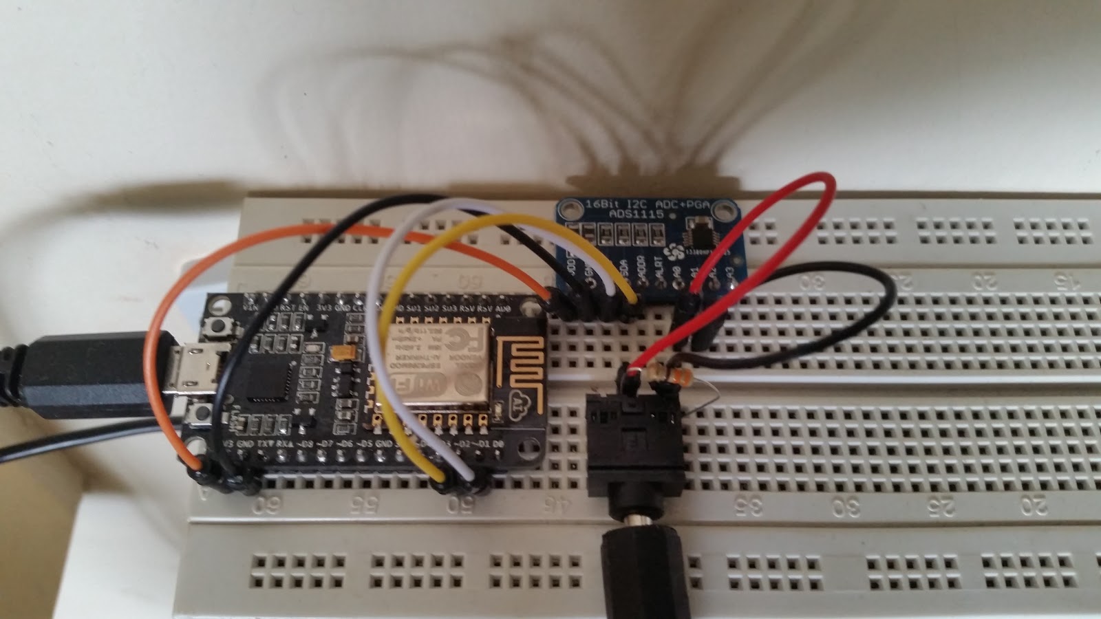
So after a bit of research I decided to roll my own on a breadboard using the ESP8266-12E based NodeMCU module. I started with a basic version is for apparent power only. To keep component count low and the circuit as simple as possible I used an ADS1115 breakout in differential mode eliminating the need for bias resistors. The hard part is getting a licensed electrician to wire up the clamp on current sensor to the main wire coming into the premises. Since we have only 1 channel we are going to monitor overall power rather than power per circuit.
Apparent power energy monitor with ESP8266
After the fact I made a Fritzing diagram showing how-to wire up the prototype on a breadboard. Powering the NodeMCU near the switchboard might be an issue as well, so I installed a DIN rail power socket, this will come in handy for real power measurement later on.
Fritzing diagram of apparent power energy monitor
One of the downsides of the ESP8266 approach however is the high current consumption (300mA or so) of the module and the fact that small block transformers used for voltage sensing will experience power factor shift under this load. This makes powering the system and measuring real power using the same transformer difficult, it can however be done with proper calibration.
NodeMCU Energy Monitor including power supply and voltage sensing
 The next bit is getting proper code to run on the NodeMCU. I chose to use the module in Arduino mode with the excellent work done here. For code inspiration I used Emonlib from the OpenEnergyMonitor project. I made some changes to read the current via the ADS1115 instead of directly via the inbuilt ADC, increased the integration period and patched in a square-root approximation method. The resulting code can be seen below.

The data from the monitor gets uploaded every 20seconds or so to Thingspeak. This makes it easy to plot graphs and analyse the data for appliance specific spikes, at the expense of losing control over it and some privacy. If you want to keep it all in house it is better to use something like EmonCMS.
Multi-day energy use graph(uncalibrated)