Showing posts with label arduino. Show all posts

Friday, February 27, 2026

Copilot + Arduino CLI + Saleae: Driver Development for V93XX

I have been spending time building out the V93XX_Arduino library for Vangotech energy-monitoring ASICs, and this is one of those projects where tooling makes or breaks momentum.

The pairing that worked best for me was:

The short version: Copilot gets you to a plausible driver quickly, but the logic analyzer gets you to a correct driver.

V93XX driver workflow walkthrough

Why this trio works

Developing protocol drivers is usually a game of “spec says one thing, silicon does another thing”.

If you rely only on serial logs, you can miss timing and framing issues. If you rely only on captures, you can waste hours writing boilerplate and one-off scripts. Using these three together gives a tighter loop:

  1. Copilot proposes code and tests from your intent
  2. Arduino CLI compiles and flashes quickly from scripts
  3. Saleae confirms framing, parity, baud behavior, and CRC bytes
  4. Copilot helps refactor after you learn what the bus is doing

In practice, this turned the V9381 UART ChecksumMode and waveform/FFT work from a stop-start activity into a repeatable pipeline.

Project context: V93XX_Arduino

Repository: whatnick/V93XX_Arduino

The library currently covers:

  • V93XX_UART for V9360 and V9381 UART modes (including address pins and checksum modes)
  • V93XX_SPI for V9381 SPI paths (faster acquisition, up to MHz clocks)
  • Examples for baseline comms, waveform capture, and FFT

Useful docs in the repo:

Practical workflow

1) Start with a machine-checkable baseline

Before touching hardware, run the local CRC and framing tests.

python tools/test_checksum_mode.py

If this is red, do not flash anything yet.

2) Use Copilot for structured implementation work

I get better results when prompts are specific and constrained. Example prompt:

Implement V9381 UART read path with explicit ChecksumMode behavior.
Keep Clean mode strict and Dirty mode permissive.
Add unit tests for CRC-8 edge cases and frame parsing.
Do not change public method names.

Copilot is strongest here at:

  • Building test scaffolding quickly
  • Keeping repetitive register access code consistent
  • Producing incremental refactors after captures reveal protocol edge cases

3) Consume datasheets with PDF MCP and keep them in-repo

Before generating more driver code, I now ingest the vendor datasheet with pdf-reader-mcp so Copilot can work from extracted register tables and command framing notes.

My workflow is:

  1. Commit the original datasheet PDF to the repository, for example under docs/datasheets/v93xx/.
  2. Use PDF MCP to extract the high-value sections (register map, UART/SPI timing, checksum/CRC rules, waveform buffer details).
  3. Save extracted artifacts back into the repo as text or markdown notes, for example docs/datasheets/v93xx/register_notes.md.
  4. Prompt Copilot using both code and extracted notes so generated changes are tied to concrete datasheet language.

This gives you a versioned paper trail from silicon docs to driver behavior, which is very useful when reconciling captures from the logic analyzer.

4) Compile and flash with Arduino CLI

For ESP32-S3 targets, this keeps the build deterministic and scriptable:

arduino-cli board list
arduino-cli compile --fqbn esp32:esp32:esp32s3 examples/V9381_UART_DIRTY_MODE
arduino-cli upload --fqbn esp32:esp32:esp32s3 --port COM3 examples/V9381_UART_DIRTY_MODE

PowerShell users can run the project helper script:

.\tools\run_automated_tests.ps1 -Port COM3

That pipeline can run unit tests, compile, upload, serial verification, and optional capture/analysis phases.

5) Validate on-wire behavior with Saleae

The logic analyzer phase is where protocol assumptions get tested.

For UART work:

  • Confirm bus settings (baud, parity, stop bits) match the target mode
  • Verify frame boundaries and inter-frame timing
  • Check CRC byte placement and value against expected payload sum/complement logic

If using the helper scripts in this repo:

python tools/capture_v9381_uart.py
python tools/analyze_checksum_captures.py [capture_dir]

This gives a concrete report of expected vs observed CRC and whether behaviour matches Clean vs Dirty semantics.

What changed in my debugging habits

Old approach

  • Edit sketch
  • Upload
  • Stare at serial output
  • Guess

New approach

  • Ask Copilot for narrow, test-backed change
  • Build and flash with Arduino CLI from script
  • Capture with Saleae and compare against expected frame math
  • Feed mismatch details back into Copilot for targeted fixes

It feels closer to hardware TDD than trial-and-error firmware hacking.

Trade-offs and cost notes

  • Arduino CLI is free and excellent for repeatable CI-style local loops
  • Copilot is a paid productivity tool, but pays for itself when protocol code churn is high
  • Saleae hardware is not cheap, but it can save days when parity/timing/CRC bugs are subtle

If you are doing serious serial or SPI driver work, a logic analyzer is not optional for long.

Troubleshooting notes that keep coming up

  1. Wrong serial configuration (especially parity) can look like random CRC failure.
  2. Upload success does not imply runtime protocol correctness.
  3. Dirty mode can hide issues by design; keep a Clean mode path for strict validation.
  4. Keep datasheet extracts in-repo so Copilot prompts reference real tables, not memory.
  5. A scripted workflow (pdf-reader-mcp + arduino-cli + capture + analysis) beats ad-hoc manual steps every time.

Closing

For this V93XX work, the winning combination was AI-assisted coding plus old-school instrumentation.

Copilot helps me move faster, Arduino CLI keeps the loop reproducible, and Saleae captures keep me honest.

If you are building protocol drivers, treat those as complementary tools, not alternatives.

Saturday, March 18, 2017

Piezo Activated Drumlights - The PCB

I feel like once you have learnt one software tool in a particular domain to an intermediate level, you can pick up another in the same domain without much fuss. Only if you are too new or too entrenched with a tool do you feel the sunk-cost fallacy and have a higher barrier to switching to something new when circumstances change.

Nightly build I am currently using
I started my adventures in ECAD using Eagle and built up quite a bit of familiarity with it, I would like to say to an intermediate to advanced level. I also built up some assets i.e. libraries and projects. To unlock more features I spent a few hundred dollars on the maker edition. However as with all software, there were niggling bugs and gripes. One of them was lack of proper 3D support, another was lack of proper slots when exporting gerbers, well slots/mills that hackvana would accept. On the hackvana IRC channel KiCAD was mentioned often and I was encouraged to switch to it. The final straw was the acquisition of Eagle by Autodesk and subsequent switch to subscription based pricing.

Eeschema of Arduino Nano drumlights
So finally after much dithering, I decided to switch to KiCAD as my main ECAD tool in the beginning of February 2017. It has been a fun couple of month translating my Eagle knowledge to KiCAD and dealing with the vagaries of a rapidly evolving tool. So far I am loving it. The first PCB I designed using KiCAD was an Arduino Nano Shield using the template provided to work with my Drumlights project. I took the PCB design as an opportunity to add a battery charger and piezo charge amplifier using a TLV2771 opamp.

KiCost in action as a BOM tool
One of the Eagle features I miss is the forward-back annotation between the PCB and the schematic. In KiCAD the association between a schematic symbol and associated footprint and nets is done using a third tool. This way there is no need for duplicate footprints per device for commonly used pad patterns e.g. SOT-23 or TSSOP-16. All devices using this footprint can share a common PCB element and only differ in schematic element. However this also means that changes in the PCB and are not automatically propagated back to the schematic. The backward link will be coming soon according to a recent roadmap. So I am living nightly-to-nightly in anticipation.

PCBNew view of Arduino Nano Drumlights
The other feature I like about KiCAD is the seamless 3D support, especially in the recent builds.There is dual support for usual VRML for pretty rendering and associated STEP files for export to other CAD files particularly FreeCAD. I downloaded step files for parts not already in the library from Molex, JST of GrabCAD and populated them with some scaling and rotation onto the PCB. You can see the resulting internal KiCAD render below. Next came sending the boards to Fab, a lot of hackerfriendly fabs directly support Eagle .brd files, now there is increasing support for KiCAD as well.

KiCAD Ray trace render of Drumlights PCB
Oshpark can directly process KiCAD - kicad_pcb files to associated gerbers and board orders. This reduces the number of clicks to ordering a prototype and eliminates potential errors and filenaming issues when creating Gerbers, since KiCAD does not really have detailed DRC and CAM job settings like Eagle.

.kicad_pcb file directly imported in Oshpark
One of the valuable lessons I learnt which I have had issues with Eagle in the past as well (obviously I trusted community review of KiCAD libraries too much) was to always double check library footprints against the datasheet. The N-channel Mosfet schematic symbol was meant for a through hole part and when paired with a SOT-23 footprint things were not in the right place. So when testing I ended up with turned on mosfets being fed with 3.3V from the microcontroller from drain-to-source essentially shorting the output. Luckily no magic smoke escaped before I spotted it and pulled the power. You can see the picture here of my hack to salvage the erroneous PCB's using the SOT-23 at 45degrees. I have tested this board with LED strips and it works as expected.

Diagonal mosfets to correct for footprint mix-up
PCBs.io is another cheap option for getting good quality prototype PCB's if you are prepared to wait. However they do not support direct KiCAD upload. If you follow the Oshpark's Gerber generation guide to create gerbers and drill files they should work in PCBs.io as well. This is what I did when ordering my test boards, after a couple of revisions via Oshpark. Overall my experience with KiCAD has been very positive. The community is fun and responsive. There are some great ancillary tools like StepUp mentioned above and KiCost which I used to instantly generate BOM for my board and order all parts from Mouser in minutes.
KiCAD Gerbers rendered in PCBs.io

If you are interested in my KiCAD experience and general principle of piezo activated drumlights you can keep tabs of my hardware and software via github.

Wednesday, November 25, 2015

Dedicated Energy monitoring with the ADE7763

After building the NodeMCU based energy monitor with an external 16 bit delta-sigma ADC i.e. the ADS1115 I started looking into solutions which were more accurate and cheaper.

I came across some work by Skye Sweeney with the ADE7763. He had built a prototype on breadboard and wanted to monitor lots of channels so the cost of sensors became prohibitive and he set the project on hold. I am attempting to measure only a single phase and disaggregate the data later by post processing, so a single ADE7763 should serve my purpose.

I set about building a breakout board for the sensor using the reference design in the datasheets and ordered it from Oshpark. This is where I made an error in my rush. I did not check the footprint the element14 library provided against the real chip. So I ended up with a board with TSSOP footprint for a SSOP chip. Should have printed the PCB 1:1 and checked with a real chip. At least the error was found while prototyping and not in production. I bent the package pins a tiny bit to squeeze it in and proceeded to assemble the breakout.

I could not quite get the SPI bus to work on the ESP8266 NodeMCU, it kept resetting the Watch dog timer. With the ESP it is often a power issue. So for a quick test I hooked up the breakout to a Teensy 3.1 and loaded Skye's code without the multi-sensor bus stuff. It worked on the first go and started dumping RMS voltage and current registers. The only thing to be careful about is the rather limited 1v peak-to-peak input range. Otherwise this chip is great with dual 16bit d/s ADC's and all the code for RMS and registers for offset removal. At about 1/2 to 1/3 the price of the ADS1115. I have uploaded some standalone  breakout testing code to github - Arduino ADE7763.

For accurate measurements this sensor can be connected to AC line using Shunt resistors for current measurement instead of a CT sensor and a direct volatge divider ladder to measure the voltage waveform instead of an isolation transformer. This makes the chip MCU unfriendly and subject to mains voltages. The SPI bus should be isolated with optocouplers when using this mode.


Meanwhile I have tested the sensor using my basic load bulb and CT clamp and voltage and current waveforms are picked up just great. At some point I will build up the courage to create a high voltage / phase accurate measurement rig.

Wednesday, September 9, 2015

Experimenting with Energy Monitors

After a spate of high electricity bills and trying to save energy by turning things off randomly I decided to do it the proper and scientific way by experimenting and collecting plenty of data.

In the days of bitcoin mining high energy bills were the norm. Now they miners have all moved to better homes and I am left with myriads of run of the mill appliances. Identifying the energy hungry beasts is not trivial.
Initial attempt at current measurement with DSO-Nano
The Open Energy monitor site has a plethora of ideas and some quite good Arduino and Raspberry Pi based designs for energy monitoring. SeeedStudio also has a couple of designs intended for energy monitoring use with an option to use an LCD or Oled screen, which I quite like. The downside of both these options however is the wireless component. The EmonTx option uses the RFM12/69 as the wireless transciever and the SeeedStudio option uses the nRF24L01+, both options require custom and expensive receiver hardware attached to an always on data-logging system.

Seeedstudio Energy monitor with nRF24
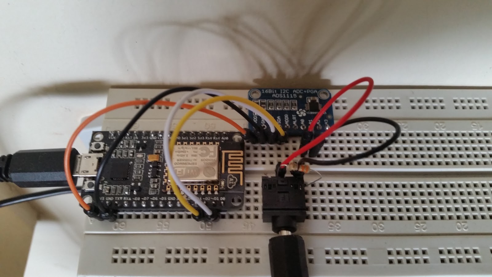
So after a bit of research I decided to roll my own on a breadboard using the ESP8266-12E based NodeMCU module. I started with a basic version is for apparent power only. To keep component count low and the circuit as simple as possible I used an ADS1115 breakout in differential mode eliminating the need for bias resistors. The hard part is getting a licensed electrician to wire up the clamp on current sensor to the main wire coming into the premises. Since we have only 1 channel we are going to monitor overall power rather than power per circuit.
Apparent power energy monitor with ESP8266
After the fact I made a Fritzing diagram showing how-to wire up the prototype on a breadboard. Powering the NodeMCU near the switchboard might be an issue as well, so I installed a DIN rail power socket, this will come in handy for real power measurement later on.
Fritzing diagram of apparent power energy monitor
One of the downsides of the ESP8266 approach however is the high current consumption (300mA or so) of the module and the fact that small block transformers used for voltage sensing will experience power factor shift under this load. This makes powering the system and measuring real power using the same transformer difficult, it can however be done with proper calibration.
NodeMCU Energy Monitor including power supply and voltage sensing
 The next bit is getting proper code to run on the NodeMCU. I chose to use the module in Arduino mode with the excellent work done here. For code inspiration I used Emonlib from the OpenEnergyMonitor project. I made some changes to read the current via the ADS1115 instead of directly via the inbuilt ADC, increased the integration period and patched in a square-root approximation method. The resulting code can be seen below.

The data from the monitor gets uploaded every 20seconds or so to Thingspeak. This makes it easy to plot graphs and analyse the data for appliance specific spikes, at the expense of losing control over it and some privacy. If you want to keep it all in house it is better to use something like EmonCMS.
Multi-day energy use graph(uncalibrated)

Thursday, December 25, 2014

Reflow oven controller with Multimeter and Arduino

After a few boards I got sick of soldering 0603 components using a soldering iron and started looking into using solder paste and hot air. I bought a hot air rework station from Rhinotools. It looks nice, but is rather noisy to use, and I find myself going for the iron always instead of the hot air gun.
The next step in the soldering tools exploration was a classic toaster over reflow. The boards I usually solder are rather small and not panelized, so I do not need a large oven. The smallest decently built oven cheap oven I could find was a K-Mart Homemaker 14L model with 1300W heating power. I also backed an Arduino Leonardo based reflow controller on Kickstarter - ControLeo2. While waiting for the controller to arrive from the US, I got itchy fingers and started hacking together a controller from bits I had lying around.

The ControLeo2 is impressive in being a 4 output reflow controller, to fully utilise this I ordered 4 cheap Fotek relays. They are rated at 25A, and the elements in the toaster consume about 3A each, so there is plenty left over. I would have liked to get a Crydom relay, but they are rather expensive. There is plenty of space in the controller compartment to fit all the 4 relays in, what I will control with them is another matter. Only 2 are needed to control this particular oven as it stands, 1 for the top and 1 for the bottom. The other 2 are planned for the booster element and a cooler of some sort.

Mounting the relays in the case requires some angle brackets, I found these at Bunnings which exactly fit the holes in the SSR with pre-drilled holes. They are galvanised steel however, not the best for heatsinking relays, but they are a good start. I am going to make some proper brackets with bent aluminium bars, but that can wait.
The initial controller was built using the BeagleBone GPIO's. There is the popular Adafruit GPIO library, but I used the less widely used PyBBIO since it has an included reflow oven controller code. My fork is modified to read temperature from a Digitek 4000ZC multimeter over the serial port using the FS9721 python library. A lot of multimeters, including some of the UNI-T models use this controller, so the adaptation should be useful for anyone with this multimeter at hand and not necessarily a MAX31855 breakout board. The SSR's are wired to the BeagleBone GPIO's via a ULN2003 relay/solenoid driver I picked up at Jaycar.
The BeagleBone arrangement though quite nice lacked a few features in the existing code, particularly support for curve editing and proper PID control. So I looked into another Python based toasterReflow controller - picoReflow. This one has even snazzier GUI and lots of options to create new curves and calculate cost in cents per reflow. I decided to try something different this time and replaced PyBBIO using my Arduino's GPIO capability, since a lot more people probably have Arduinos compared to BeagleBones and Raspberry Pi's. So my EeePC replaced the beaglebone as the main controller, taking in the readings from the DMM over 1 USB port and feeding out the SSR control signals to the Arduino over another USB port. This closed loop looks something like this:

Oven -> Thermocouple -> Digitek 4000ZC -> EeePC -> Arduino -> ULN2003 -> Fotek Relays -> Oven

Overall this works quite well for me and I hope it is useful for someone else attempting to build an oven without a fancy controller with just the bits at hand, yet achieve a nice controlled profile.

Thursday, February 28, 2013

Where am I .... all the time

Okay lets start by clearly stating the futility of position, every defintion of position requires a reference frame. It would be pretty messy to define where I am relative to the centre of our galaxy at all times, the super-massive blackhole makes measuring time there pretty messy as well. I could define my position better in ECEF or ENU or in most cases Platte Carre. I set out to build a project which could define where I am at all times for the posterity and essentially keep a track of my spime. My spime is the only thing I have absolute natural rights to, everything else can be taken away and be subject to argument with sufficient legal juggling. Come to think of it even the personal spime is not inviolate, meh reading to much Hannu Rajaniemi. Android My Tracks is pretty good, but a phone sometimes feels like too many eggs in one basket, I don't want to leave it lying around in the car dash gathering sunlight.

The project is mainly based on a Seeeduino stalker board with a convenient Bee socket. I plugged the UBlox Neo-6M based GPS Bee there. Data logs go to a 2GB SD card and Lipo power is backed by a 1w solar cell. The GPS constantly spits out NMEA strings which get logged to the SD card as long as power and space is available. A log with 2 days worth of data took up 45Mb, so I can hold about 3 months of data. Unfortunately the 2000mAh battery died after 2 days of continous use, with some solar recharge while in use. Since the battery death, in order to prevent melt down in harsh sunlight and continuous use, I have added a USB charger option as a stop gap. This should hold the fort till I plug in the quartz/heat powered charger for use while hiking and the mini windmill for use while wind surfing. Eventually the SD card will blow off into star dust after I have had my fun and extracted and time and location of said fun, but hey SD cards are more expensive per-ounce than gold.

Tuesday, November 15, 2011

OSDC 2011 - MiniConf Redux

Last couple of days I hung around Canberra attending the OSDC in ANU and drinking gallons of orange juice and tomato juice in pubs.

The morning was spent catching up on PHP. I learnt stuff like traits, hiphop (via Facebook),  odata (via Microsoft),

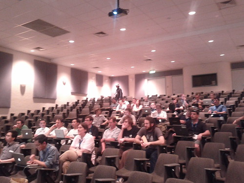
On the first day I assisted Jody in running the Geotools workshop. Only a small fraction turned up with laptops, so it was a rather cozy session. I met some old acquaintances again - Matt Paget from CSIRO Black Mountain (TERN) and Kelvin from Adelaide Uni now at DSD.
Osdc geotools students
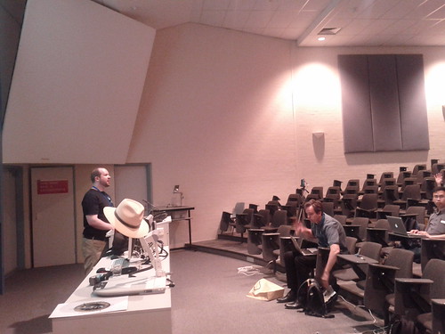
Osdc geotools the teacherWe celebrated the after conference party at a quiz night, where team OSDC consistently got the lowest score and I learnt trivia like there have been 5 different images of the queen on the Australian coins. The second day was a mad Arduino rush. I acquired an Arduino Uno via Littlebird and lots of wisdom concerning making PCB's and making lights blink in fancier and fancier ways.
Apparently once you have fallen in love with Ferric Chloride you will never go back to anything else for etching. I now just need to find someone to come and have a look at my etchings.

Tuesday, August 23, 2011

Week of fun Hardware - Octocopter, Extruder, Kinect Poetry and MIDI 2 Life

Last week was an amazing overload of gadgets (with some flying to Canberra and hanging out at a bar with E-Tax release manager thrown in). First highlight was the Octocopter at UTAS - it is indeed a massive beast with 8kg border line payload, paltry 5 minute endurance, but it gets the kit off the ground. I also saw some of the amazing work Arko has been doing with Bundler, PMVS and Meshlab.

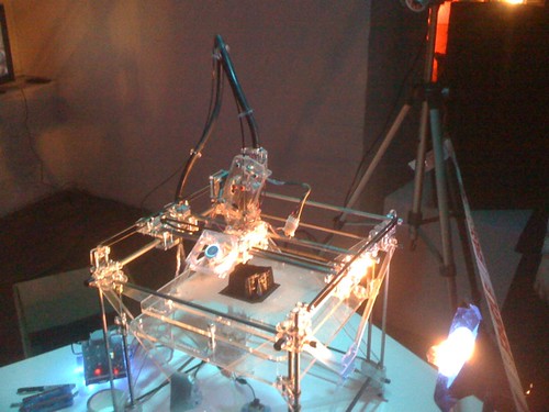
 The night before I went to Canberra, there was a Sound2Lights show in the Long Gallery with lots of cool gadgets. Including the aforementioned Rep-rap extruder printing out music (Joseph) , a Kinect you had to do a weird dance to get to put words in place (and possibly rhyme and form poetry - Aaron) and of course Nick's game of life with music controlling organisms rendered in Unity 3D.

Thursday early in the morning I flew off to Canberra to help deploy Australia wide terrain, but that is another story.

Wednesday, April 6, 2011

Expanding the Arm-AVR menagerie (Training Pandas)

I have recently acquired some more hardware - a Tincan tools Trainer for xM and a Pandaboard. Sometimes I feel embedded should start with an 'A' - for ARM and Arduino.

Word of caution in the new kernels the serial ports on the xM appear at /dev/ttyO1. Look in /proc/tty/drivers - OMAP-SERIAL  /dev/ttyO     253 0-3 serial.

You will need this little tid-bit to program the trainer. The programmer seemed to be atleast respond to avrdude when fresh out of packaging:

avrdude: stk500_getsync(): not in sync: resp=0x20avrdude -V -F -c stk500v1 -p m328p -P /dev/ttyO1 -b 57600 -U flash:w:blink.hex

avrdude: stk500_getsync(): not in sync: resp=0x20

It was not working anyway, but can I make it fail with 0x20 predictably ? So I got fancy and forwarded the serial port over the network. The beagle acts as a serial port server and the host machine acts as the client. This is plain tcp, but you can build an ssh-tunnel or whatever. The serial port is redirected with interceptty. The same failure was observed.

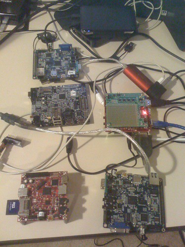
The embedded platforms menagerie, and Avrs thrown in

So I forked out some cash and got myself an ISP cable. This let me load the arduino bootloader using avrdude and the instructions here. After the first bootload, avrdude and avrgal can both push blink.hex to the arduino bootloader, but fail to perform further writes due to the lack of the software reset (stty -F /dev/ttyO1 hupcl). So I resorted to how the arduino visual IDE does things and eventually I used the Arduino.mk in /usr/share/arduino and built up a blink.hex which was significantly larger than the pure Makefile based one. This one supports loading and reloading via avrgal. The first attempt made an arduino bootsector virus as av500 put it.

Now that all is hunky-dory in the tincan + beagle-xM world, it is time to attach a few peripherals to the arduino and watch it squirm.

Wednesday, June 2, 2010

Keeping a level head for 3 minutes - Arduino Razor IMU

It has been a really tough week, to cap it all off my passport has gone walkabout. On Friday my 3 minute thesis competition is coming up and I have been rattling off prattle about penguins and farmers in front of my iPhone timer. So far I either take 2 minutes or 3.5. The idea is to talk about the work on vegetation in Macquarie island while gaining sympathy points for trying to save wildlife. SAR is difficult to interpret by humans and we stand on the shoulders of statistics and electromagnetics founders such as Gauss and Maxwell. Ultimately the full importance of vegetation parameter retrieval.

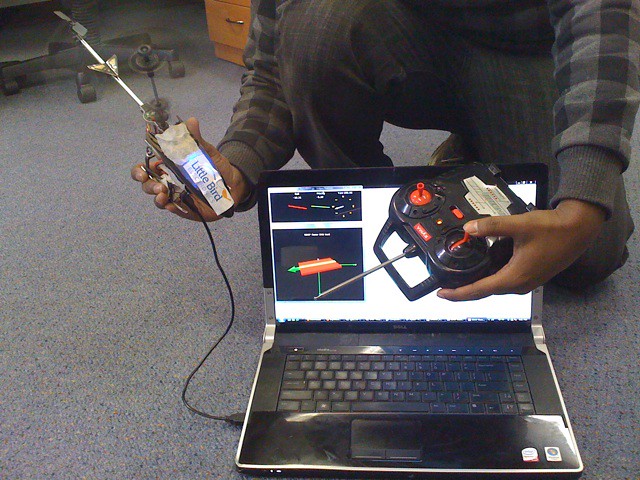
If I can keep a level head for 3 minutes then it should not be too hard for an Arduino to give me 50 stabilized attitude readings per second. I recently acquired the 9DOF Razor IMU and works quite nicely with the supplied Python scripts. I attached to my heli and flew it around a bit, no major pushes due to the magnets in the motors. Next I will attach an Xbee to it and stream the attitude data out of the heli.

Saturday, May 22, 2010

Arduino + Beaglebord + Other bits = Autopilot

So I have had a minor set-back with the el-cheapo motors on the quadcopter. No surprises there. Time to chin-up and get better motors and start building the second iteration. This one will feature stereo vision, barometer and the razor imu for positioning instead of the 3DM GX2. I am about to test the beagleboard to arduino connection over i2c, I will have to ensure that I attach some level converters this time to isolate the 2 voltage levels and have reliable operation.

I think the razor IMU will start life hooked to an Xbee and strung down from my hand flown co-ax. It is much lighter than the microstrain box and the little heli should be able to lift it. Both the xbee and the razor operate at 3.3 volts so no level shifting needed, the heli seems to provide some 4.2 volts which is rather odd for a lipo pack.

Helping with the lift calculations is this little tool. With a 1400kV motor i can turn bigger propellors and possibly prevent burn-outs. Better order some more el-cheapos with ESC just in case the controller is toasted as well.

Monday, February 1, 2010

Italian made Arduino - almost like an affordable Ferrari

I received my Arduino today, surprised to see Italy stamped all over it. A little flag on top, a little map at the back and proudly stenciled "Made in Italy". Almost made me feel like a performance car owner, not that I am into such stuff. The IDE is simplified but effective, after much pains with the AVR Butterfly el-cheapo TTL-RS232 converter which made it impossible to put it in programming mode - the ease of the Arduino was a breath of fresh air. Atmel should take a leaf and make some decent dev boards and installers which run on hampered systems such as Vista ( could not get AVRStudio to install).

The 1st thing to do on microcontrollers is obviously to make a blinking LED, so I went ahead and made a 50Hz PWM timer interrupt based one - using the nifty millis() function. I believe our quadcopter will not run for 50 days and it is perfectly safe to use. On the other hand it gives us only around 1/20 resolution in ESC based motor control, if this is found to be too coarse other solutions using proper PWM will need to be sought.

For production I also got an Arduino Mini for use in production. Needs some soldering and off-board FTDI USB-Serial, but it is super small in all SMD. Finally I did some waving around of the blinking LED to demonstrate the 50% or so duty cycle. Works well since there is a power LED in the background providing constancy. Now have to make 4 of these and an I2C instruction parser to set the duty cycle on each channel.