Showing posts with label energy monitor. Show all posts

Thursday, May 7, 2020

ADE7816 Energy Monitor

I have been meaning to try out the ADE7816 Single-phase 6 current channels energy monitor for a while. However time has been lacking for the last couple of years. Finally I have a working version with successful board bring-up and a semi-working Micropython driver, with an Arduino driver in the works.

PCB Design

The PCB design process for this was not easy mostly due to a footprint choice mistake on my part. I had placed the 5x5mm QFN part instead of the 6x6mm QFN part in KiCAD. This made the DRC fail everywhere in standard settings. However it ended up being a collaboration opportunity with Greg Davill who loves to practice and photograph bodging stuff. So I now have a work of art at hand instead of a non-functional board.

I am even debating whether to place the rest of the parts and possibly take away from the dead-bug awesomeness. Next time need to order parts in advance and make sure I do 1-1 prints to verify footprints before pulling the trigger on PCB's.

Energy Montor Details

Now to more about the energy monitor. This ASIC features 3 single-ended and 3 differential current inputs and a single-phase voltage input, all in very compact 40-pin 6x6mm QFN package. In fact the PCB is large on purpose to accomodate ease of use with stereo-jack type current clamps. The main usage would be in standard households where there are typically 3-4 lighting circuits, 1-2 socket circuits and dedicated Air Conditioning circuit. A single energy monitor could be built to monitor all channels using a single-ASIC and leave out fancy NILM stuff from worrying about the lights. The socket circuits could have anything plugged into them and can potentially have point-of-load monitoring instead of breaker board based monitoring. All this translates to more data being generated for IoT platforms and some sensible firmware work needs to be done to handle that.

ADE7816 Driver Development

This is still work in progress. I have done some initial exploration to find prior art. Nothing exists yet from Arduino however there is some register lists from a Javascript driver written for the now defunct Intel Edison.

Intel never quite had the maker market pinned right to market that board, it makes me sad to think of all the engineering ours sunk into a now defunct platform. Open-source software / hardware helps us salvage some of that. I also sped up the register listing by copy-pasting the ubquitous table from the ADE7816 datasheet and dropping it into a Jupyter notebook to parse all the registers, not as fancy as the Pdf parser I had built before, but much more reliable.

My driver development follwed the now tried and tested Micropython + Jupyter Notebook + Logic Analyzer path. I used an ESP32 feather as host processor with standard micropython loaded and probed the SPI bus with read-write packets for known registers until the protocol gave in and started responding with some values. The ASIC is super versatile in supported protocols - I2C Slave, SPI Master and SPI Slave modes are all viable. So developing a fully functional driver supporting all the possible modes will take a while. The initial work so far is on the SPI slave mode since all my other work in DIN rail and Featherwing formats is linked to the SPI bus, however the I2C mode can be really interesting for host-processors with fewer pins and flaky SPI support (while having solid I2C support - like the Onion).

If anyone is interested in driver development I am happy to send you a board or you can get one yourself from Oshpark, Aisler or PCBWay. Once the drivers mature I will list it for a wider audience on Tindie.

Sunday, March 3, 2019

Kogan Energy Monitor Teardown - Sonoff-Pow in a wall plug

After doing a tear-down on the TPLink Wall Plug energy monitor I found mentions in Australia of the much cheaper Kogan Alternative. So I decided to get a couple of them see what makes them tick as well.
General Assembly of the whole unit

TL;DR - The Kogan one is cheaper because it uses a bare metal (non-linux capable) CPU and a PWM output type energy monitor (without intricacies of a SPI protocol and calibration). It is essentially a repackaged Sonoff Pow.

The details of the build are packages in sections as I discovered them.

LV and Buck converter


The LV section consists of two separate cricuits:
  1. Relay to switch the load
  2. Buck converter to rectify and convert 240v to 5v to power electronics
The diagram below presents both of these sections. The Buck converter is basically the toplogy found in many aliexpress products. Perhaps with the difference of being unisolated (notice no slots). The relay is rated at 15A which is nice compared the TPLink product which uses x2 - 5A relays in parallel to achieve 10A.

Low Voltage (240v) Circuitry

Energy Monitor and LDO

This a 3.3v operated section which uses the super low-cost PWM output energy monitor IC made popular by the Sonoff the measure instantaneous voltage, current and hence power. The pulses are channeled to the main processor for forwarding to whatever backend Kogan has put together.

Metering and LDO

Main Processor

The design seems to have taken a standard ESP module and planted it on a basic PCB to fit in the power-plug form factor, sideways. The carries board has lots of markings and test-points making the task of reverse engineering and putting new firmware on this board almost too easy.
Processor module adapter
Marked bottom test pads of processor carrier PCB
Over all this looks like a nice certified unit which you can run your own firmware on thanks with the help of the right triangular security bit.

Sunday, November 25, 2018

Onion IoT module Python SPI

Some say China is the country of 80-20, things are complete and great to 80% , the remaining 20% of polish is left hanging. The Mediatek CPU used in the Onion IoT modules suffers from a similar shortcoming. There is an working SPI bus, but it is simplex ( OUCH!!) . Simplex means only receive and transmit can take place at a time.

For interfacing the Onion Module with Energy Monitor IC's this is a huge blocker since the typical communication flow with this IC's runs as:

  1. Write a 8 or 16 bit register address to the SPI bus
  2. Immediately read-back a 16bit value over the SPI bus while the chip-select is held low.
The proposed remedy to this after a bit of debugging and probing with logic analyzers is to directly use the user-space SPI c-library or to fix the python-spidev library with an xfer3 method which does a special write where the clock keeps going, the first bytes are written and next bytes are read.

I have started on the path for fixing the Python library on my fork. OpenWRT build system seems happy with my efforts so far. It remains to be seen if we can communicate with the energy monitor ASIC's. Contributions are much appreciated.


Sunday, November 18, 2018

TPLink Smart Plug Teardown

A while ago I remember watching a youtube video from about x10 years ago talking about distributed social network platforms running on SheevaPlugs. Fast forward 10 years, we are still in walled gardens of internet behemoths like Facebook, Twitter and Google and energy monitors are running full-linux os'es in smart plugs (albeit it is mostly OpenWRT/Lede)

The idea of re-purposing Atheros/Qualcomm router IC's as general purpose linux based controllers is not new. All those pins dedicated for ethernet ports are converted into GPIO's with proper muxing.

I have been designing one myself to fit in the DIN rail using the Onion Omega 2 as the host processor. There are some road-blocks regarding the simplex SPI bus on the Mediatek CPU.

TPLink seems to have gone the same route and built a smart-plug with and Atheros CPU. Again this blog post is meant to enrich the notes I already brain dumped on twitter.


This module is designed to be a wifi controlled relay with metering, switching upto 10A according to specs. It achieves this by using x2 5A relays in parallel. The main subsystems are:


  1. Power - Analog Devices/Linear Tech power AC-DC power IC. The footprint of this is an interesting variant of SOIC-8.
  2. Metering - This is done by the Maxim MAX71020A IC. Every electronics manufacturer worth its salt is creating metering ASIC's these days and I am excited about opportunities in making break-out boards and comparisons. TPLink seems to have bought up all the inventory of this particular Maxim IC and Maxim has a history of discontinuing low-margin lines the like MEMS accelerometers. I will keep an eye of the Poly-phase version which seems to be still in production (MAXQ3180). Overall this does not look good for the future of this particular smart-plug.
  3. Relays - x2 chunky 5v - 5A relays adorn the metering and CPU board. These provide the main functionality of the smart plug.
  4. Atheros/Qualcomm processor - This is the smarts in this smart-plug. Running standard open-wrt. The Maxim IC is of course on the SPI bus and other GPIO's are driving LED's , relays etc.
Overall the lack of supply of the Maxim IC does not bode well for the future of this Smart-plug. It may find fun alternative uses as an always on linux node.

Another Energy Monitor - Neur.io Teardown

Looking at other energy-monitor designs has been a past-time of mine and I recently the chance to teardown a Neur.io energy monitor installed along with many Tesla power-walls in Australia. This one had had some feedback of high voltage over the modbus and had fried itself. Despite best intentions with TVS suppressors etc. it could not take it anymore.

In this blog post I will enrich some of the content I already posted on twitter with some more in-sights in energy monitoring and additional elements regarding current clamps.

 This is the proper blogpost alluded to in the twitter thread. All the image content is already in the thread. Blogs simply allow greater structure. The meter is essentially composed of:


  1. Current samplers with 1ohm burden resisors attached to CT's - Neur.io recently announced a flexible CT design which can make it easy to install and potentially universal in measuring AC currents via induction and DC currents via hall-effect. I dropped an multi-meter probe on the burden resistors just to check.
  2. Voltage samplers as tiny encapsulated isolation transformers - This approach can introduce some non-linearity due to hysteresis and phase-shifts in the transformer, transformers are also bulky. Since the transformer is under no-load, phase-shifts should be minimal. The advantage is built in LV isolation. There is a bank of x3 transformers to account for x3 phases.
  3. Energy monitor IC's - These are from Cirrus Logic (CS5467), the documentation says the IC is mainly for the Japanese market. Neur.io seems to be successfully using it in North American and Australian market.
  4. Main processor and wifi - Unfortunately the unit I had was going back to Tesla under RMA, so I did not have chance to take of the shield and probe the processor. However I would love some assistance in poking in there and exploring the possibilities of custom firmwares.
  5. Modbus - The meter has a modbus I/O port to communicate with other systems e.g. Inverter and Battery charge controller.
  6. Power Systems - This is a Recom SMPS (RAC05-02SC) module keeping with my idea of keeping custom subsystems as limited as possible and reusing tested components as much as possible. I have seen a lot of energy monitors include their own power sub-systems including the Sense and WattWatchers. This increases design complexity with perhaps marginal improvements in design flexibility and BOM costs. The module outputs 3W at 5V, giving some head-room for LDO/Cap based noise filtering.
I have come to learn that DIN rails are not that popular in the North American market compared to the European and Australian market. Hence the overall brick packaging of the Sense and the Neur.io meters. Keeping the DIN form-factor requires a lot of combined mechanical and electronics design work as I have found out the hard-way. It is currently in my pipeline to create break-out boards for the CS5467 and test them out with common micro-controllers.

Thursday, December 14, 2017

Sense Energy monitor teardown - sampling in MHz

Recently I obtained a Sense Energy monitor via US from Margaret of BitKnitting. She is doing a very interesting neighbourhood energy efficiency project. As usual I could not contain my curiosity and opened it up to have a look. I will start off with an analogy - the closest bit of open-source kit that I have to do half the amount of analog functions as the Sense is the PRUDAQ on the BeagleBone wifi as pictured below.
Beaglebone Wireless + PRUDAQ
The case is very well built from high density plastic, however it is clipped together neatly and easy to take off without permanent damage. The wifi antenna is screwed on with a neat water sealed connector. The power/voltage and current sampler connectors are Molex Microfit and Nanofit respectively. I rather liked the Molex Nanofit and adopted it for my own DIN Rail sampler board.
Enclosure and main boards
Inside this very nice exterior are a couple of very dense sandwiched PCB's. One is Green, almost a generic power supply board, but with additional function to sample the split phase AC in the North American grid. The other is a black board where the magic happens. It is essentially a beaglebone wireless with a custom energy monitor system put together using high-speed ADC's and a CPLD
Green Power board, Black Digital+Analog board

Main PMIC, same one is used on the BeagleBone Black
The image below shows the subsection that performs energy measurements, it is composed of x2 high sample rate ADC's (14bit 2MSPS) and an Altera Max V 64pin CPLD. I assume the cells inside the CPLD perform the reading from the ADC's and multiplication/accumulation to compute energy usage, then transmit computation results to the TI CPU.

Custom energy monitor with high-speed (2MSPS) ADC's and Altera CPLD

Wifi Module
Switcher IC's on power supply board

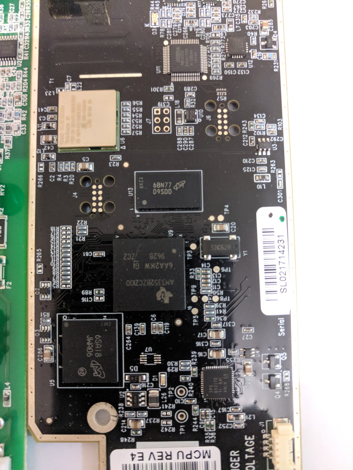
The main CPU is a Linux compatible AM3352 CPU from TI. It does not have a PRU co-processor like the one used on the BeagleBone, hence the need for a CPLD to perform some of the real-time computation required.
TI Arm CPU and RAM/Flash

Overall the Sense energy monitor hardware is a great design, though a bit specific to the USA market. I am looking forward to a release in the Australian market. The purchase to study one was certainly worth it. Now off to install my own linux build on it and send the data elsewhere.

Thursday, June 29, 2017

3G Energy Monitor - WattWatchers teardown

Tear-downs are always done in a spirit of learning and admiration. Having built some hobby electronics I really appreciate what goes into laying out a mixed signal PCB as well as one that has high and low-voltages on the same board and is subject to regulatory compliance both for electrical characteristics and RF emissions.

I was handed some detailed WattWatchers images by a client and I did some mark-up of what goes into them based on previous experience of how energy monitors are put together. It is a 2-board design with an SMD PCI connector joining the boards. The PCI connector passes the power and current-voltage signal up to a vertical board.

I shall call the bottom board power and sampling  board and the side-board metering, CPU and network board. The first image below shows one side of both boards. The power supply board features a hefty cap-drop supply with assortment of fuses and TVS, as well as the aforementioned PCI connector. The vertical board features a large 3G module and associated Telstra sim slot, I assume the SIM is linked to a custom M2M plan which costs a few dollars a month.

The other side of the vertical board features the most interesting goodies. On the left half it has a low-noise / high power voltage regulator from ST (presumably needed to feed the hungry 3G modules), as well as a low-power MSP430 MCU with a couple of large old-school tantalum caps. The right side of this board (separated by a row of what is most likely transient suppressors or isolation amplifiers) are a couple of Analog devices 3-phase energy monitor IC's. The isolation section indicates the presence of 9 analog channels which corresponds to 3-phases and 6-CT's. The 2 ADE7880's share a single clock crystal presumably buffered. There are also a bunch of passives to perform 50Hz filtering.

The other side of the bottom board also featured in this image contains the voltage divider to sample the AC-phases and some current-multiplier/burden resistors to convert the current measured by the CT's into a voltage value. There is also another LDO on this board to presumably power one side of the isolation amplifiers, nothing too high power. This LDO must be at the end of the cap-drop system so the neutral or phase on it is at high voltage and generous dob of insulating snot is providing extra protection. The insulating snot can also be seen at the top-left corner of this board where the phase and neutral(?) or 2 phases are too close together for comfort/compliance.

WattWatchers has done a great job packing a lot of features into an M2 DIN rail enclosure without resorting to many off the shelf modules and pre-built components except the 3G module. I am hoping to re-use some of the concepts here in my ATM90E36 based design.

Friday, May 19, 2017

ATM90E36 Dev-kit for 3-phase AC Metering

ATM90E3X Devkit PCB 5x5
After successfully building the single-phase energy monitor with the ATM90E26 there has been lots of interest in the 3-phase version. Being an open-hardware project, many people have created remixed and derived versions as well. After a while I started receiving requests to assist with the code for ATM90E36, the 3-phase version of the Energy Monitor chip. However I did not have the hardware to test the code, so I put together this basic devkit to access the SPI bus and easily inject voltage and CT signals to take the ATM90E36 through its paces. This is the first board I have designed based purely on user demand rather than to scratch my own itch, since I don't have 3-phase supply at home.

Design station for Energy Monitor PCB
I ended up making a 12V AC targeted design like my single-phase version with stereo jacks on board for directly connecting current transformers. The test PCB also has few LED's to show energy pulses and is basically a low voltage version of the 3-phase 4-wire Atmel/Microchip reference design. I restricted the size of the PCB to 5x5 for hackvana's specials category. These can also be obtained from PCBs.io if you want to send some credits my way. The final touches to the design were put in my shed drawing power from my solar panels and marine battery during a now notorious Adelaide blackout.

Logic analyzer SPI protocol analysis

This chip uses the 16-bit SPI mode while most Arduino compatible CPU's only implement an 8-bit SPI mode, so bit of SPI sequencing was necessary to get the results. A cheap Saleae compatible logic analyzer went a long way to pinning down the protocol and getting the right values. You can see the protocol analysis fot the ATM90E36 in the logic analyser screenshot.
Test rig with Teensy and logic analyzer
The ATM90E32 and ATM90E36 share the same footprint you can choose either chip when building the board. The ATM90E36 has slightly more functionality including data dumping over DMA with the chip in SPI-master mode.The unused pins on the ATM90E32 can be grounded when using the board. My library for the ATM90E36 should work for the ATM90E32 as well with meaningless results for the CRC check code. I am re-writing the library specifically for the ATM90E32 while I design some featherwing hardware around it as well.
I took the whole thing for a test to the Hackerspace in Tonsley who graciously provided me a set-up involving a 3-phase variac, an isolation transformer and a 3-phase load bank with wire wound resistors. The test set-up can be seen in the video below. I actually managed to blow up the load bank by pushing 12V AC through a 2ohm load rated for only couple of amps, maths failure there. Just excited to be able to play with the 3-phase at an isolated low voltage. While the load ran it gave nice readings on the monitor which I had previously calibrated using a single phase at a time.
For the next test to have a safer and more controlled conditions I am trying out several DAC's to simulate Voltage and Current waveforms with relevant phase shifts. That is another blog post and project altogether.

Wednesday, December 7, 2016

Aliexpress DIN Rail Energy Meter teardown

The best way to learn is often by looking at solutions others have come up with. "Monkey see - monkey do" is pretty much part of the engineering process. While at University we wrote a top-scoring piece on how Apple scooped Creative in making a portable digital hard drive backed music player with great design and even greater marketing. When doing a tear down for inspiration and copying ideas always be wary of patents.

I am planning to move my ATM90E26 + Wireless Stack Energy monitor into a more industrial DIN rail format. To get an idea about how things are packaged inside a DIN rail energy monitor I ordered a no-patents cheap energy monitor with pulse output from AliExpress. The brand is Eastron, they also make quite affordable 3-phase versions which I am going to look at next.
DIN rail enclosure including wiring diagram
Once the meter arrived I did not even plug it in (in Australia an electrician will be required to properly install it due to the cutting of the live line to place a shunt and other modifications). I put a screw driver through the QC sticker, popped open the clipped on enclosure and proceeded to have a peek inside. What I found was a house of PCB's stacked around a transformer to make best use of the place inside the enclosure. The following labelled photos show the various parts.
Profile view with stacking

The stacking places the main processor board with AFE + MCU and LCD display on top, the transformer and associated carrier and high voltage safety stuff (Varistor and PPTC) at the base. The base PCB also carries the Live/Neutral connectors and a bulky current shunt. One vertical PCB is the power supply, voltage and current waveform sampler and the other is an isolated pulse and modbus output board (Modbus chip is unpopulated in my pulse only version).
Bottom view with safety components and current shunt
The voltage sampler uses a resistor ladder of 4x270K resistors in series with a relatively small voltage sampling resistor. The PCB is not heavy on expensive board to board connectors, which allows a modular system and swapping of boards, instead it relies of solder fingers on board edge to link the boxy shape together. The same board also carries the power supply module derived from a regulated full wave rectified output from the transformer. I am not sure if the transformer is isolating, it does not need to be since the isolation occurs at the end stage with a couple of optocouplers. The voltage sampler and the current shunt are obviously non-isolated.
LDO for dual voltage level output and 4 pads for 2 waveform signals
All the magic of actual energy monitoring then happens in the Vangotech V9811S with includes a 8052 MCU for driving the LCD and other functions such as Modbus support. I am planning to power it up with a 3.3V/5V supply and feed it waveforms from my low voltage AC test rig and observe the readings. I also have 3 phase version from Eastron on order and a few engineering samples from Vangotech for their 3 phase ASIC to build a low cost/ low voltage Dev kit like I did with the ATM90E26 Featherwing.
Anatomy of the head, MCU + AFE, EEPROM and an old school LCD

Wednesday, November 30, 2016

Adelaide Maker Faire 2016

Last Sunday (6th of November 2016) I spent almost the whole day on my feet talking to people at the Adelaide Maker Faire. It was a great event and I have been looking forward to it for almost a full year.

It took a bit of preparation in putting together a demo that would pass the electrical safety requirements and be tested and tagged. I chose to use a compact fluroscent lamp and a halogen lamp as my demo loads to illustrate the impact of power factor on energy measurements. The modern CFL's have notoriously low power-factor due to the uncompensated choke in them. I ended up making an earthed and a double insulated enclosure for my demo.
Earthed Test lamp box
Double insulated test lamp box


Earthed lamp fixture with Perspex lid

The main PCB on show was the Energy Monitor Featherwing with the ATM90E26 on-board. This does very quick and accurate measurements and I chose to send the data over serial to a laptop for graphing rather than use the rather crowded wifi and 3G environment at the faire. It also makes a more compelling demo since I can sample and display the power every second rather than every 15s with thingspeak (faster with workarounds still only down to 2s due to 8 channel limitation, must investigate running my personal Blynk or EmonCMS server).
ATM90E26 Low-voltage Energy Monitor (perspective view)

ATM90E26 Energy Monitor top view
My overall display was pretty minimalist since I focused on getting the hardware working rather than producing any marketing material. I ended up handing out notes written on the spot with my details on them. There was fair bit of interest and some people shared ideas with me on how they had solved the same problem themselves. I hardly got time to check out other displays myself. Next time I will make sure I have someone to relieve me. I did manage to have a peek at the Daleks and saw a toddler hop out of a solar car, sights you can only see at a Maker Faire. This was southern hemispheres biggest and the buzz was amazing.

Maker Faire setup with lamps on
At the end of the day the organisers of the Maker Faire handed me a maker of merit badge which I am quite proud of and next year I plan to show up with even more projects.

Monday, October 10, 2016

ATM90E26 + ESP8266 Energy Monitoring

Before I commit a design to a PCB, I usually make a messy jumpers everywhere version on a breadboard. This is not always possible for a full complex design, often sections get committed to PCB and then modules find a home on the overall breadboard prototype.

This has been the fate of my ATM90E26 Breakout. I plan to eventually make it into a single board /accurate wifi enabled Energy Monitor. For now it is living next to a NodeMCU on a breadboard. The ATM90E26 has the flexibility to be accessed both over SPI and UART. However the SPI mode it supports is only Mode 3, which is an unsupported mode of the ESP8266 Arduino stack. So I ported my ATM90E26 Arduino interface code over to UART mode with CRC check and everything worked okay after a few days of head scratching. You can find it on the UART branch in github.

I would like to build a self-powered energy monitor, so I pulled out a venerable 7805 and added it to a half-wave rectifier from the 12V AC-AC transformer used for voltage waveform sampling. When I was using a full-wave rectifier in the past the overall DC voltage was too much for thr 7805 to regulate without a heatsink, however with the 1/2 wave version, the diode takes care of dropping half of the voltage leaving the 7805 functional without a massive heatsink.

I calibrated the set-up with some magic multipliers found using the datasheet, maths and my 116W calibration lamp and it all works like a charm as shown in the video below.

There seems to be some noise leakage onto the UART when AC signals are applied, I will attempt to rectify this with an optoisolator. However a simple reboot of the ESP8266 platform seems to quickly fix any software serial communication issues. Meanwhile I am putting it all together into a featherwing form factor for PCB manufacture.

Wednesday, May 18, 2016

More Energy monitoring - ATM90E26 Breakout

After designing and testing the ADE7763 based Energy Monitor Breakout Board, I started looking around for cheaper and more modern alternatives.I came across the Atmel ATM90E26 Smart Metering IC with dual communication options - UART/SPI and multiple metering modes (tamper proofing with current sensing on live and neutral). However the Evaluation Module (EVM) from Atmel is over-engineered and targeted at an enterprise audience. It is around $800 from Mouser Australia. I guess it needs to be so to comply with creepage/clearance requirements for handling 240V AC signals. This however puts it beyond the reach of a dabbler such as me.
Assembled ATM90E26 Reference design with low-voltage components

So I set about extracting the low-voltage only components from the Atmel Reference Design and placing them on a PCB. Atmel generously provided me with 3 sample IC's to go with my PCB's from OSHPark, thereby saving me around $750 in testing their IC.

Checking SPI mode - Mode 3 works
Then I went on the usual hunt for prior art in interfacing this code with a microcontroller and came across this post in /r/diyelectronics which interfaced the ATM90E26 to a Raspberry Pi. Ryzee sent me the code and assisted me in choosing the right SPI mode (mode 3 in this case) which lets a Teensy talk to the ATM90E26. The code is now available as an Arduino sketch.
ATM90E26 RMS Voltage mesurement test harness
I built a low-voltage test rig to see if the voltage ADC works okay and all seems to check out. Full blown Energy Measurement tests next. Meanwhile I have placed the couple of boards I have on Tindie to gauge interest for a larger batch. Let me know if you would like to test this modern Energy Monitor IC on the cheap.

Wednesday, January 20, 2016

Extending Energy monitoring - ADS1115 Grove module and ADS1115 Featherwing


After selling a few kits and populated boards of the NodeMCU Energy Monitor on Tindie, I started receiving feedback from people in the real world using my design. One of the main requests was the ability to support more channels, the other was miniaturisation suitable for fitting in 1 or 2 unit DIN Rail enclosures.

I addressed the request for channels by developing my own energy monitoring specific ADS1115 breakout. In addition to the core IC it includes 3.5mm stereo sockets for connecting the popular YHDC CT sensor and a couple of Grove connectors for chaining multiple boards together. Using this mechanism and the core NodeMCU energy monitor, one can monitor upto 7 current channels.

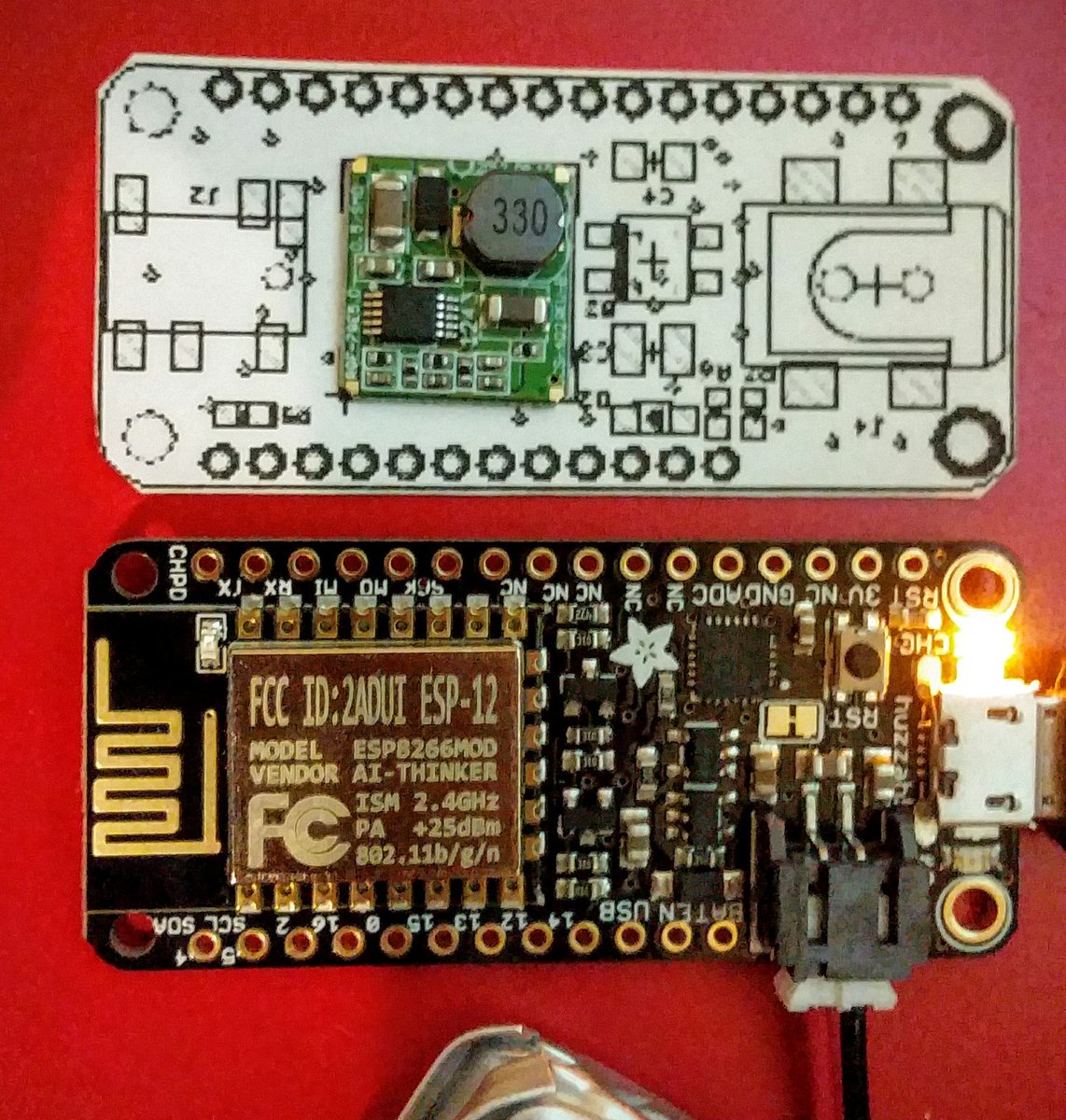
The issue of miniaturization is adressed by choosing a smaller form factor and feature rich ESP8266 breakout, namely the Adafruit feather. As a side effect we gain access to all the other boards using the feather form factor and all the other stackable featherwings.

During the design of the Energy Monitor Featherwing I integrated the ADS1115 onto the same board instead of using a breakout  (switched to 0603 parts to make it more compact) and used an SMD version of the Recom 5V Buck converter.

The featherwing can be mounted with stackable connectors under the Adafruit feather. Leaving the top free for display OLED for realtime power display or just weather or bitcoin prices vs energy usage.

Wednesday, November 25, 2015

Dedicated Energy monitoring with the ADE7763

After building the NodeMCU based energy monitor with an external 16 bit delta-sigma ADC i.e. the ADS1115 I started looking into solutions which were more accurate and cheaper.

I came across some work by Skye Sweeney with the ADE7763. He had built a prototype on breadboard and wanted to monitor lots of channels so the cost of sensors became prohibitive and he set the project on hold. I am attempting to measure only a single phase and disaggregate the data later by post processing, so a single ADE7763 should serve my purpose.

I set about building a breakout board for the sensor using the reference design in the datasheets and ordered it from Oshpark. This is where I made an error in my rush. I did not check the footprint the element14 library provided against the real chip. So I ended up with a board with TSSOP footprint for a SSOP chip. Should have printed the PCB 1:1 and checked with a real chip. At least the error was found while prototyping and not in production. I bent the package pins a tiny bit to squeeze it in and proceeded to assemble the breakout.

I could not quite get the SPI bus to work on the ESP8266 NodeMCU, it kept resetting the Watch dog timer. With the ESP it is often a power issue. So for a quick test I hooked up the breakout to a Teensy 3.1 and loaded Skye's code without the multi-sensor bus stuff. It worked on the first go and started dumping RMS voltage and current registers. The only thing to be careful about is the rather limited 1v peak-to-peak input range. Otherwise this chip is great with dual 16bit d/s ADC's and all the code for RMS and registers for offset removal. At about 1/2 to 1/3 the price of the ADS1115. I have uploaded some standalone  breakout testing code to github - Arduino ADE7763.

For accurate measurements this sensor can be connected to AC line using Shunt resistors for current measurement instead of a CT sensor and a direct volatge divider ladder to measure the voltage waveform instead of an isolation transformer. This makes the chip MCU unfriendly and subject to mains voltages. The SPI bus should be isolated with optocouplers when using this mode.


Meanwhile I have tested the sensor using my basic load bulb and CT clamp and voltage and current waveforms are picked up just great. At some point I will build up the courage to create a high voltage / phase accurate measurement rig.

Tuesday, November 3, 2015

The SeeedStudio ESP8266 Contest and resulting product on Tindie

A few weeks back I participated in the SeeedStudio ESP8266 project design contest with my NodeMCU based Energy Monitor. As in all popularity contests I had to ask my friends to help me out and vote for me as often as possible. I had the most views, but not the most votes. Still I ended up in the second place which I am quite happy with.
Fully assembled NodeMCU Energy Monitor - Sensors plug in at the bottom
With such encouragement I decided to get a PCB fabricated for my Energy Monitor project and put it up for sale on Tindie. This is my first electronics project for sale and apart from some local interest, I have made an export sale to the UK. Deciding how to put the project together for sale is quite new to me. I have a certain skill-set but other electronics enthusiasts may not share them. Should I just offer blank PCB's, which other's might as well get from OSHPark or DirtyPCB ? Should I offer a through-hole kit along with the PCB and take the interested party through the soldering order ? Should I put everything together as SMD in my oven and offer the kaboodle including NodeMCU and the rather expensive ADS1115 ? What about the current and voltage sensors ?
NodeMCU Energy Monitor "mostly" Through-hole Kit

There are also component and PCB sourcing issues as outlined in a previous post. Tindie offers some flexibility in this regard letting me set-up various tiers and options. My single product listing becomes effectively a stratified listing catering for buyers with multiple electronics proficiency levels. I might start offering the 100A clamp of current sensor and 12V transformers from YHDC as part of my kit, to make gathering of all the components easier. With bulk manufacture in SMD, cheap mass produced NodeMCU modules and knock-off ADS1115's I might be able to get the total cost down to USD20 unshipped. Which will put the design at par with these non-web connected versions of the same. The design will also be far cheaper than the custom web-connected offerings from Efergy and Wattcost, mainly because these consumer grade products also provide a data hosting service complete with apps and websites. The NodeMCU Energy Monitor leaves the user in charge of their own data and requires certain knowledge of IoT platforms to take full advantage of it. The number of players (AWS, Thingspeak, Bluemix etc.) in the IoT data hosting arena is increasing daily and I am sure people automating and sensorising their homes will appreciate the choice, rather than be locked in with the server hosted by the hardware vendor.

The remaining hurdle is of course shipping, it cost me about USD14 to ship 2 units to UK from Australia as small parcels. Where as China post shipping costs are minimal. Logistics - another hurdle holding back small scale production in Australia. The only long term sensible thing to do will be to manufacture in China and exploit the logistics there. All said and done I am pretty happy with my $50 sale, at least it has paid for the electrician who installed the energy monitor.
Fully installed NodeMCU Energy Monitor - Black YHDC transformer, current sensor inside the enclosure

Wednesday, September 9, 2015

Experimenting with Energy Monitors

After a spate of high electricity bills and trying to save energy by turning things off randomly I decided to do it the proper and scientific way by experimenting and collecting plenty of data.

In the days of bitcoin mining high energy bills were the norm. Now they miners have all moved to better homes and I am left with myriads of run of the mill appliances. Identifying the energy hungry beasts is not trivial.
Initial attempt at current measurement with DSO-Nano
The Open Energy monitor site has a plethora of ideas and some quite good Arduino and Raspberry Pi based designs for energy monitoring. SeeedStudio also has a couple of designs intended for energy monitoring use with an option to use an LCD or Oled screen, which I quite like. The downside of both these options however is the wireless component. The EmonTx option uses the RFM12/69 as the wireless transciever and the SeeedStudio option uses the nRF24L01+, both options require custom and expensive receiver hardware attached to an always on data-logging system.

Seeedstudio Energy monitor with nRF24
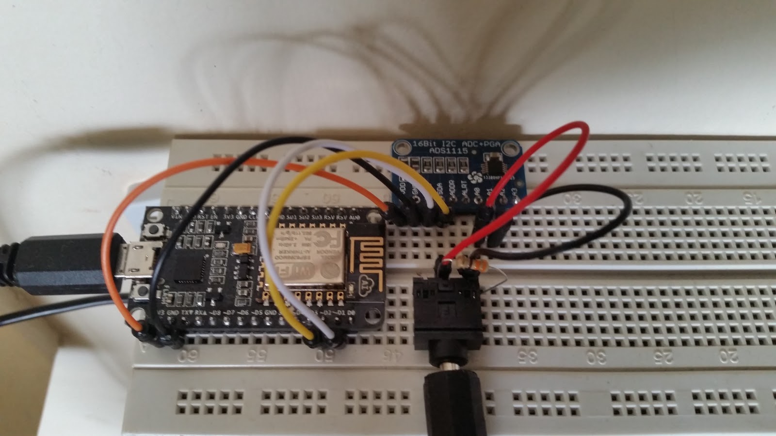
So after a bit of research I decided to roll my own on a breadboard using the ESP8266-12E based NodeMCU module. I started with a basic version is for apparent power only. To keep component count low and the circuit as simple as possible I used an ADS1115 breakout in differential mode eliminating the need for bias resistors. The hard part is getting a licensed electrician to wire up the clamp on current sensor to the main wire coming into the premises. Since we have only 1 channel we are going to monitor overall power rather than power per circuit.
Apparent power energy monitor with ESP8266
After the fact I made a Fritzing diagram showing how-to wire up the prototype on a breadboard. Powering the NodeMCU near the switchboard might be an issue as well, so I installed a DIN rail power socket, this will come in handy for real power measurement later on.
Fritzing diagram of apparent power energy monitor
One of the downsides of the ESP8266 approach however is the high current consumption (300mA or so) of the module and the fact that small block transformers used for voltage sensing will experience power factor shift under this load. This makes powering the system and measuring real power using the same transformer difficult, it can however be done with proper calibration.
NodeMCU Energy Monitor including power supply and voltage sensing
 The next bit is getting proper code to run on the NodeMCU. I chose to use the module in Arduino mode with the excellent work done here. For code inspiration I used Emonlib from the OpenEnergyMonitor project. I made some changes to read the current via the ADS1115 instead of directly via the inbuilt ADC, increased the integration period and patched in a square-root approximation method. The resulting code can be seen below.

The data from the monitor gets uploaded every 20seconds or so to Thingspeak. This makes it easy to plot graphs and analyse the data for appliance specific spikes, at the expense of losing control over it and some privacy. If you want to keep it all in house it is better to use something like EmonCMS.
Multi-day energy use graph(uncalibrated)