My students have finally taken some inspiration from the mechanical engineering folks and started on building a PID controller for the quadcopter using
simulink blocks and various experiments to measure the angular acceleration produced by the motors. They are still far from having a rigid-body simulation of the system but apparently the PID controller in simulink can be stabilized. Another challenge will be to port the PID controller to Python, building a rigid-body simulation can be attempted with
PyODE.

They had also been asking for a block diagram and/or circuit diagram. So I obliged with an
Inkscape block diagram, circuit digrams are best left to the manufacturing professionals of Arduino and Gumstix.

The measurement of angle with time shows non-constant angular acceleration, but the curves can still be fitted with a second order polynomial. The angular rate curves look even more quadriatic, indicating increasing acceleration with time.
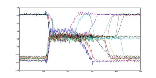
Extracting the acceleration from this should be pretty straight forward as long as we fit a polynomial to a relatively safe part of the dataset. I think a fair number of reptitions and logs of the same experiment will be needed to smooth out the wiggles.

No comments:
Post a Comment